3D Printing versus CNC Machining
Here are some quick points to consider when deciding between using our 3D printing laser sintering process versus our CNC machining process to produce your part.Part Size
With the 3D printing laser sintering process, specifically Selective Laser Sintering (SLS) for plastics and Direct Metal Laser Sintering (DMLS) for metals, part size is limited to the volume of the machinery’s build chamber (XxYxZ mm). Our machines have different build chamber sizes so be sure to review the machinery specs relative to the part size you are considering. Also note from a cost perspective that the larger the part (especially in height), the greater the build time required.
Part Geometry & Design Innovation
Also, since the laser sintering process only uses powder material where required, parts can be produced with less weight yet achieve excellent strength properties. This is one reason laser sintering is increasingly used for the production of aerospace and medical parts.
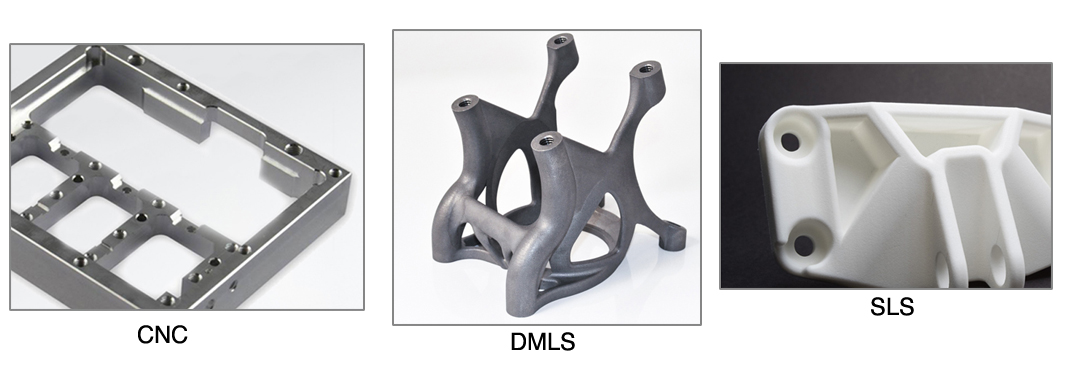
Our 3D printing machines can achieve variable tolerances, depending on the part which may not be enough for some critical part features. With CNC machining you can achieve low tolerances which can make a big difference if you’re producing an assembly aid, manufacturing fixture or any in-process tool with a long service life.
When consulting with our service bureau be sure to provide the critical dimension tolerances required. Often we can recommend design adjustments to optimise the part build, such as increasing certain wall thicknesses.
Costs and Speed
3D printed parts can generally be built in less time than machined parts, as set up requirements are minimal and tooling is not required, both of which add to production times and associated costs. Our 3D printing machines run unattended – regardless of how complicated the part being built – resulting in less labour input.
Though 3D printing material powders are expensive, powder is only applied where required, resulting in less waste than CNC machined parts. However depending on your requirements, 3D printed parts may require post machining, adding to production costs.
Prototype vs Full Production
3D printing is generally more economical for one-off prototypes or small batch runs. The process offers more flexibility to both evaluate and refine your part design, since you only need to update your CAD/CAM files before undertaking further build iterations. Evaluate a part’s form, fit, appearance and functionality before moving into production.
CNC machining better utilise economies of scale once a part reaches larger production volumes. Large production runs allow machining set up and tooling costs to be amortised more effectively, reducing costs per unit produced.
Surface Finish
Surface roughness is defined as the recurrent irregularities of a part surface which are inherent in the production process. CNC parts typically have a much smoother surface finish, whereas 3D printed parts are more porous with a slight grainy texture.
This is usually not an issue for prototyped parts, but may be an issue for final part production. Part features such as seal grooves are likely to require post machining, threads may require cleaning up, critical bores may require boring out if roundness is critical.
Conclusion
CNC machining is ideal for the manufacture of large parts, parts with straightforward geometric designs, parts requiring high precision, high-quality surface finishes and large scale production. Set up and tooling requirements will incur higher labour costs and longer lead times.
For first time users or those looking to compare 3D printing methods, there are design principles to be considered when using Selective Laser Sintering (SLS) to ensure high quality and cost-effective results. These principles relate to a wide range of part design applications.
Machinery
EOS P396
- Standard Lead Time: 5 to 10 days
- Materials: PA 2200
- Build Volume (XxYxZ mm): 340x340x600
- Building speed (depending on material): up to 48 mm/h
- Laser Type:[CO2′ 70W/
- Precision optics: F-theta-lens
- Layer Thickness: 0.1mm
- Scan speed during build process: up to 6 m/s

Steps
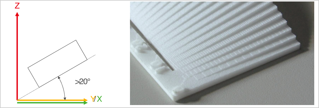
To avoid steps on your surface, the angle of the plane should be 0° or >20° to the X-Y area;
visibility and size depend on layer thickness
Hinges
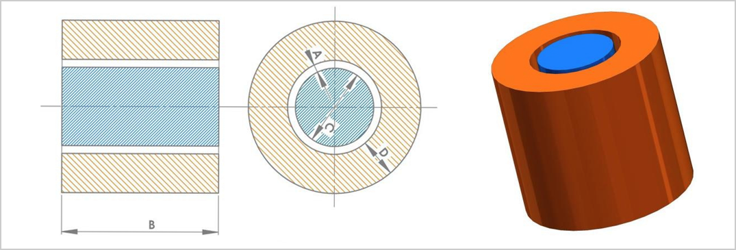
Gaps (A) for Hinges:
- x/y: 0.3 mm – 0.5 mm
- z: 0.5 mm – 0.6 mm
Variables:
- gap between bush and bolt (A)
- length of the hinge (B)
- diameter of the bolt (C)
- thickness of the surrounding
- bushing (D)
- building direction
With advance geometries smaller gaps are possible
Fonts
Minimum font size 14 suitable for every direction
Smaller fonts possible depending on such factors as:
- building direction
- inside / depth of font
- outside / height of font
Sans serif font is recommended

Part Tolerances
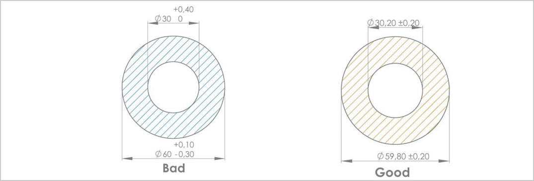
Depending on whether you build the part to the same specifications as the CAD design, it may be necessary to change the measurements from an unsymmetrical to symmetric tolerance zone, as the laser sintering process only allows for symmetric tolerances.
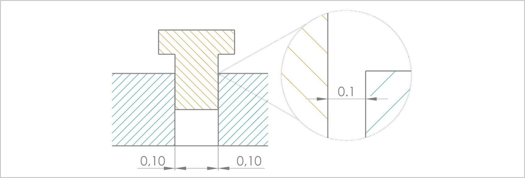
Lose Connection
Use 0.1 mm distance
A male and female part without a gap
Have a press fit only for parts not built together; otherwise see hinges
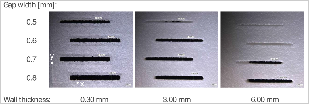
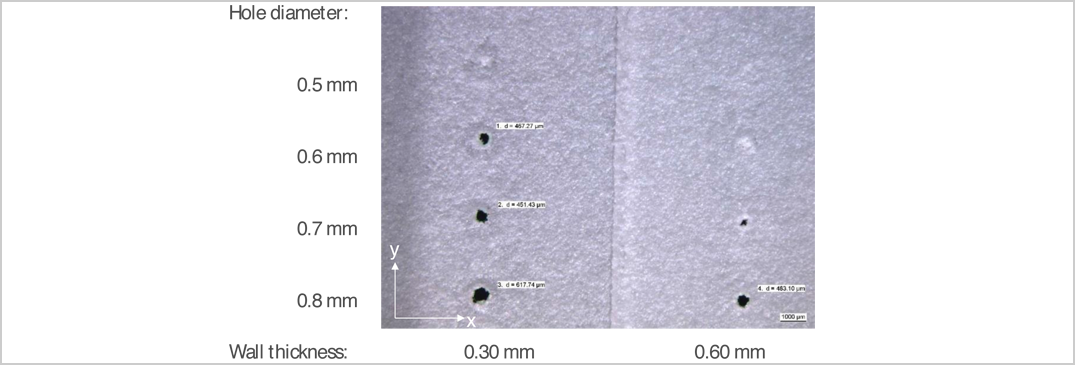
Gaps, Holes
The minimum size gap (mm) is dependent on the wall thickness (mm) of the part. In tandem, the minimum size hole diameter (mm) is also dependent on the wall thickness of the part.
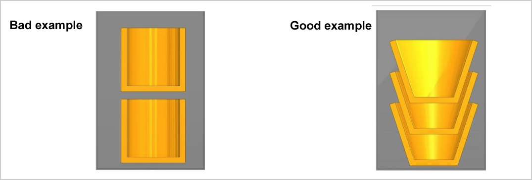
Costs
Build costs are dependent to a large extent on machine hours and powder usage. One of the best ways to reduce machine hour costs is to reduce the height (z) of the part and build volume. The example at right shows an integrated part design (fewer machine hours) versus two separate parts.
Powder Removal
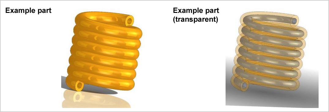
Part design needs to take into account the ability to remove all excess powder. The example at right show a part with a very long hollow pipe. Compressed air alone will not be able to remove all the internal waste powder, requiring more post processing times and additional cost.
Data Format
The interchange format is STL
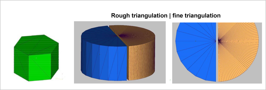
The STL file describes a surface by triangles
The file size and detail resolution is dependent on the number of triangles
Square-cut surfaces are easy to describe (pic1)
Freeform or round shape parts require a lot of triangles (pics 2,3)
A guide value for plastic parts is:
- deviation tolerances: 0.01 mm
- angle tolerances: 2°
For first time users or those looking to compare 3D printing methods, there are design principles to be considered when using direct metal laser sintering (DMLS) to ensure high quality and cost-effective results. These principles relateto tooling applications (DirectTool) such as building inserts for injection moulding tools using DirectMetal 20 powder but are also applicable to building positive parts (DirectPart).
Machinery
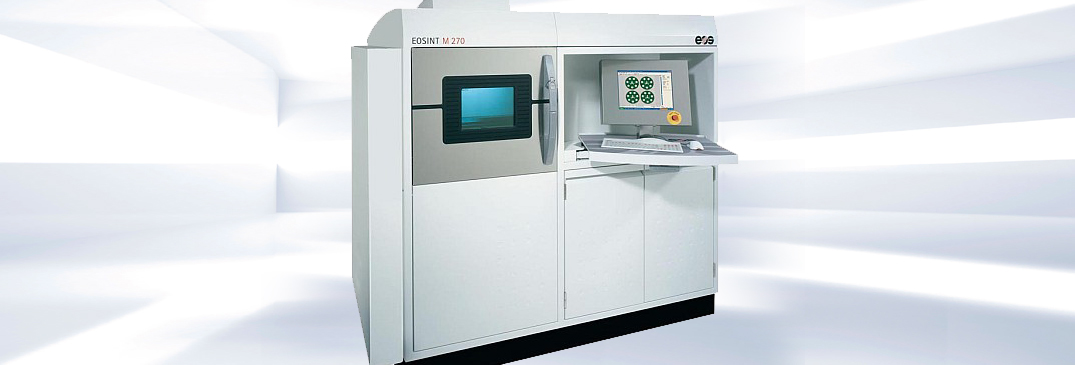
EOS M270
- Standard Lead Time: 5 to 10 days
- Build Volume (XxYxZ mm): 250x250x215
- Laser Type: Yb-fibre 200 W
- Minimum Feature Size (mm): .38mm
- Layer Thickness: 20-40 mm
- Minimum Wall Thickness: .3-.4 mm
- Operation Mode: Nitrogen
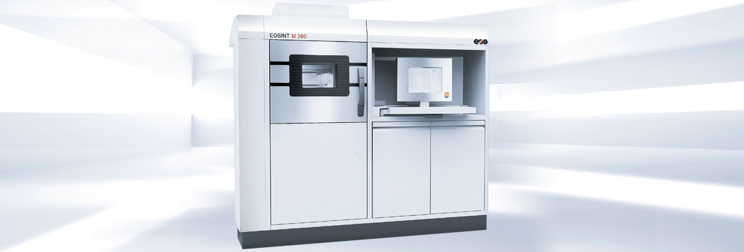
EOS M280
- Standard Lead Time: 5 to 10 days
- Build Volume (XxYxZ mm): 250x250x325
- Laser Type: Yb-fibre 400 W
- Minimum Feature Size (mm): .38mm
- Layer Thickness: 30 mm
- Minimum Wall Thickness: .3-.4 mm
- Operation Mode: Nitrogen, Argon
The DMLS process creates parts additively by fusing powder particles rather than conventional methods of material removal. This means that the conditions under which the DMLS process can be used cost-effectively depend strongly on the geometry to be built and attention should be paid to designing the geometry appropriately.
A part that can be milled with little effort should generally be milled. It usually makes sense to apply the DMLS process in cases where EDM (spark erosion), five axis milling or multiple clamping positions would normally be required. Before a decision is taken, an estimate about the production times with the different processes must be made. In the DMLS process only the relevant geometries should be built and superfluous volume avoided if possible.
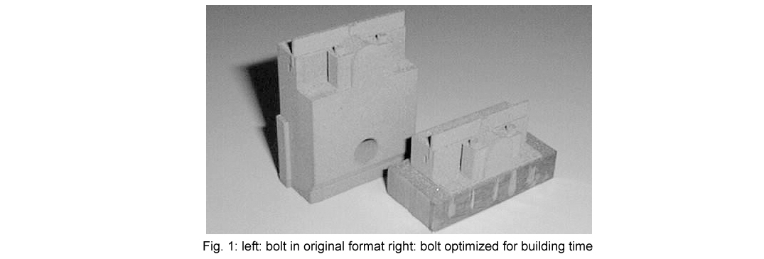
This is particularly relevant for tool inserts. As for all generative, layer-wise fabrication processes it is not the complexity of the geometry that determines production time and costs, but rather the build volume (amount of material to be solidified) and height (number of layers). The inserts should be as small as possible in x-, y- as well as in z-direction to keep the building process as short as possible and thus to save costs (Fig. 1).
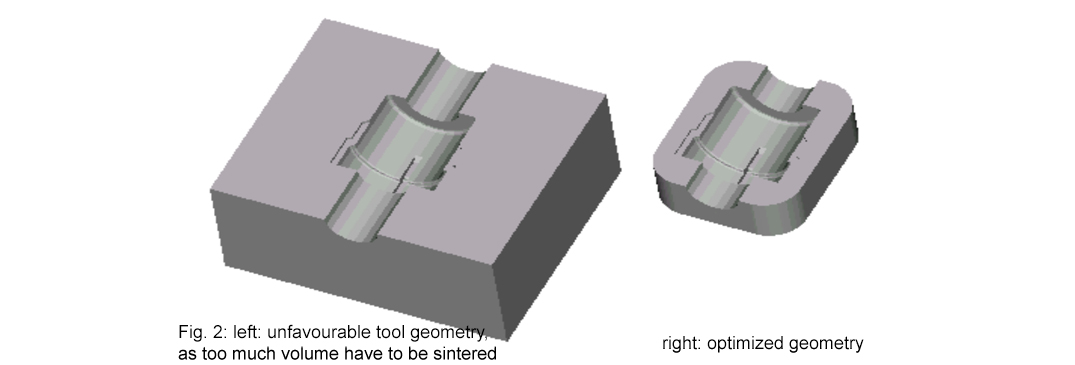
The tool insert displayed in Fig. 2 left side, is produced faster and more cost-efficiently if only the relevant geometry, i. e. the actual cavity, is built. The optimised version is shown in Fig. 2 right side. As shown, it is also preferable for external corners to be round rather than sharp.
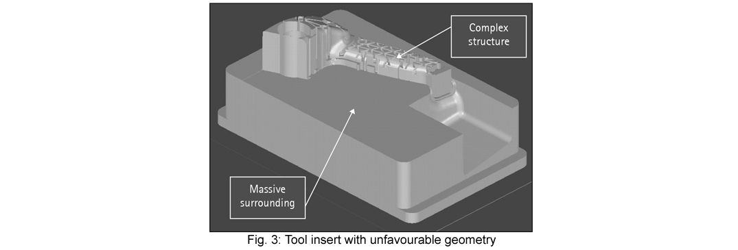
For tool cavities, a wall thickness of about 10 mm around the relevant structures is in most cases sufficient. The design of the massive substructure for the ejector side of the tool in Fig. 3 is extremely time-consuming. Here it would make sense to fabricate only the complex rib structure in the upper tool area by DMLS and to insert it afterwards into a substructure fabricated in parallel using a conventional process.
When designing the tool insert it must be taken into consideration to use the building platform, a steel plate of typically 22 or 36 mm thickness, as a part of the insert. The laser-sintered part is built on the steel plate and metallurgically attached to it, afterwards the surrounding part of the plate is removed by e.g. sawing and milling or wire cutting.
Of course it is also possible to build the parts on support structures, e. g. positive parts (DirectPart). These parts remain fixed to the base plate during the building process via a support structure and are separated afterwards by breaking away the supports. It is not possible to build “detached“ parts as can be done for plastic laser sintering.
Overhangs up to an angle of approx. 25° can be built without requiring a support structure.
2 Drill Holes / Skin & Core
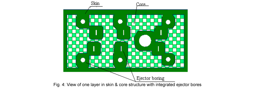
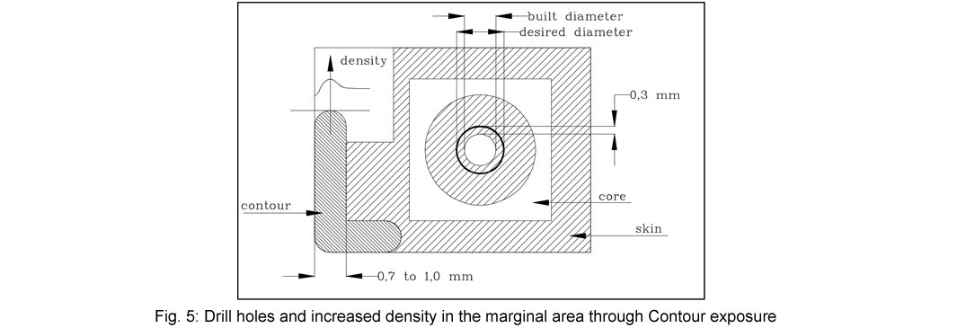
All drill holes for ejector pins, holes for fastening screws or similar features should already be provided in the CAD design. This is necessary as DMLS tools are typically built in a so-called Skin & Core structure.
Here the part volume is divided into a so-called Skin area and Core area (Fig. 4), which are exposed with different parameters during the building process and can even be built up with differing layer thicknesses. Typically, the Skin is selected to be 1mm thick in x, y and z direction and built in a layer thickness of 0.02 mm. The layer thickness of the Core is 0.06 … 0.1 mm. The Skin is exposed with building parameters which give maximum strength and hardness, while the Core is exposed faster. In this way the building time can be significantly decreased without loss of surface quality while maintaining a high part stability.
If drill holes have not been provided in the CAD file and are added later, the hole is located in the mechanically less stable core area. This can for example lead to the subsequently tapped thread breaking out.
Additionally the external boundaries of each layer are exposed as a Contour with a very high laser power which leads to a very high stability. The area of increased stability is about 0.5 mm deep below the surface. When post-processing up to this depth, the best results concerning surface quality and surface hardness are obtained.
We recommend therefore to design the diameter of the desired drill-holes in the CAD file about 0.6 mm undersized and to rebore them afterwards. The side walls of the drill-hole are then within the highest solidity area of the contour (Fig. 5).
3 Accuracy
As the parts are generated from metal powder, the surface roughness and the geometrical accuracy lies within the range of the powder grain size, which is ± 50 µm for DirectMetal 20. The resolution in the vertical direction (perpendicular to the layers) is determined by the layer thickness. For DirectMetal 20 it is typically 0.02 mm. The obtainable accuracy for DirectMetal 20 is (0.07 % + 50 µm).
4 Minimum Structures
For the DMLS process, the focussed laser beam with a diameter of approx. 0.4 mm is equivalent to the tool for fabricating the geometry. The sintering width is a little higher than the focal diameter due to heat conductivity effects.
As with other processes, structures smaller than the used tool cannot be produced, although with DMLS the “tool” size defines the minimum external feature size (e. g. wall thickness) rather than internal feature size (e. g. slot width). The minimum sintering width is approx. 0.6 mm for DirectMetal 20.
If structures smaller than this are contained in the geometry to be built, they cannot be built correctly. This must be considered carefully, especially for sharp corners and edges.
5 Slots
If there are deep slots in the geometry, it has to be taken into consideration that due to the surface roughness of vertical planes, post-processing will be necessary or draft angles must be adapted. For slots which are accessible for grinding and polishing, draft angles of 0.5° to 1.0° are sufficient. If the slot is not accessible, this value must be increased. If this is not possible for geometrical reasons, the tool should be split at this feature and the planes should be treated afterwards. The inserts are then assembled afterwards.
6 Ribs
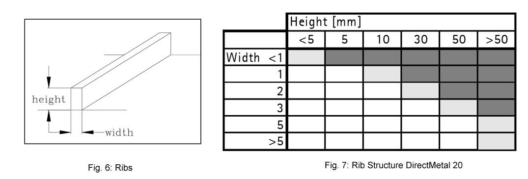
To ensure reliable performance of injection moulding tools even under high loading, it is recommended not to exceed the height-width ratios (Fig6) marked white in (Fig. 7) for DirectMetal 20.
7 Pins
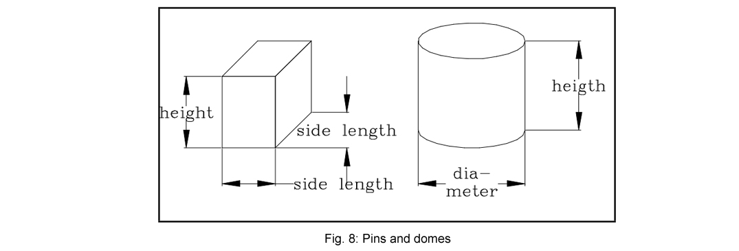
The same is valid for pins located in the tool to be fabricated.
For round geometries it is generally recommended that pins are inserted into drill-holes previously designed in the CAD file, as this enables highly accurate and very strong pins to be obtained with minimal effort.
For non-cylindrical geometries inserts should also be used for the height-length ratios (Fig. 8) as seen for DirectMetal 20.
8 Gating Channel
To avoid erosion at the gating channel (Fig 9), this should also be prepared in the CAD file. The contour exposure increases the surface hardness and thus an improvement of wear behaviour is achieved.

9 Cooling Channels
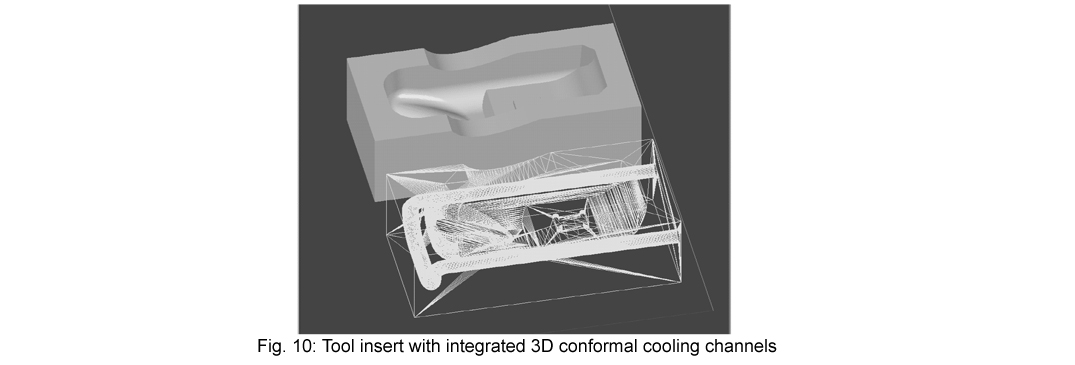
Using the layer-wise building technique it is possible to create 3-dimensionally curved cooling channels within the tool, adapted to the injection mould geometry (conformal cooling). This enables a much more effective cooling to be obtained during injection moulding (Fig. 10).
When designing the cooling channels, care should be taken to plan the connections in such a way that no unnecessary volume has to be built. For example it is possible to lay the connections directly into the steel plate. After the laser-sintering the holes are bored at the corresponding places through the steel plate and the loose powder is removed from the channels. Afterwards the cooling channels can be sealed with Epoxy resin.
10 Machining Allowances
When fitting the inserts into the mother tool, the edges are usually milled. A machining allowance of 0.1 mm to 0.5 mm should be planned on every relevant area.
It is generally not necessary and not recommended to post-machine the parting surfaces of tool inserts. These are typically post-processed by micro shot-peening and if necessary touched up with manual filing and polishing. The surface offset is added during the data preparation of the laser-sintering job if necessary and therefore does not need to be included in the CAD file.
11 Assembly Into The Mother Tool
When assembling the mother tool it is important to ensure that the parting plane load or the locking pressure of the injection moulding machine rests at least partially on the mother tool. For optimum moulding time it is also advisable to mount the inserts comprehensively in the mother tool and thus to have the pressure load rest on the mother tool during injection moulding, i. e. there should be no gap between the DMLS inserts and the mother tool.
12 Data Quality And Transfer
A basic rule is: The higher the data quality is, i. e. the clearer the design is, the shorter is the time required for data preparation, and the higher is the part quality. It is therefore necessary to remove all superfluous information from the STL data generation, which means to clean the file. All planes must unequivocally intersect with each other and be trimmed etc.
The mesh density when generating *.STL data should be not coarser than one layer thickness.
Sensible CAD settings for STL export:
-Maximum triangle size: 10 mm
-Chord error: 0.01 mm.
Polymer Powders
| Powder Material | Colour | Character | Machinery | Applications |
|---|---|---|---|---|
| PA 2200 Fine polyamide |
 |
Very fine multi-functional polyamide | EOS P 396 |  Illustrative models, functional parts/ end products, spare parts Illustrative models, functional parts/ end products, spare parts |
| General material data | PA 2200 |
|---|---|
| Average grain size | 60 μm |
| Bulk density | 0.435 – 0.445 g/ cm3 |
| SLS Part Density | 0.9 – 0.95 g/cm3 |
| Mechanical properties | PA 2200 |
| Tensile modulus | 1700 ± 150 N/mm2 |
| Tensile strength | 45 ± 3 N/mm2 |
| Elongation at break | 20 ± 5 % |
| Ball indent hardness | 77.6 ± 2 N/mm2 |
| Thermal properties | PA 2200 |
| Melting point | 172 – 180 °C |
| Finish | Sample | Remove Excess Powder | Glass Bead Blast | |
|---|---|---|---|---|
| Natural |  |
X | X | |
| Painting and Dyeing Parts | Options | Benefits | Key Points | |
| Painting SLS Parts | 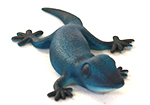 |
acrylics, enamel, varnish, oil | Smooth texture; colour appeal | Use 2-3 coats; allow to dry between coats; paint in one direction; avoid applying too much paint; use masking tape for straight edges between colours; clean brush and allow to dry before switching colours |
| Dyeing SLS Parts | 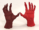 |
clothing dye (e.g Ril) | Smooth texture; colour appeal | Use small amount of dye; add as needed; mix dye in warm water; bring to boil; place in mixture for 20-30 minutes; continually reorient for even penetration; remove, wash, let dry |
| Notes: 1. Parts should be washed throughly and etched before being painted or dyed. 2. Polyamides are porous and absorb; test to ensure appropriate texture and colour; also when painting one side of a thin part or two sides different colours. 3. Dyeing is limited to one colour per part; dye pigment must be darker than current colour. 4. Painted and dyed parts will look lighter when wet; colour will darken when dry. 5. Spray the finished part with a clear coat of varnish or lacquer to seal it. |
Metal Powders
| Powder Material | Colour | Character | Machinery | Applications |
|---|---|---|---|---|
| CobaltChrome MP1 Cobalt-chrome molybdenum-superalloy |
 |
Excellent mechanical properties, corrosion and temp. resistance | EOS M 270 EOS M 280 |
 Medical devices and high temp.engineering, e.g. aero engines, turbines Medical devices and high temp.engineering, e.g. aero engines, turbines |
| Direct Metal 20 Bronze-based alloy |
 |
Good mechanical properties, very easy to finish | EOS M 270 |  Injection mould tool inserts, other tooling applications, prototype parts, fixtures, test parts Injection mould tool inserts, other tooling applications, prototype parts, fixtures, test parts |
| MaragingSteel MS1 Hardenable steel |
 |
Excellent strength, high toughness, easily machinable | EOS M 270 |  Series injection tooling, high volume production, high performance parts Series injection tooling, high volume production, high performance parts |
| StainlessSteel GP1 Stainless steel |
 |
Good mechanical properties, excellent ductility in laser processed state | EOS M 280 |  Engineering applications, industrial parts, prototypes, tooling Engineering applications, industrial parts, prototypes, tooling |
| Titanium Ti64 Light titanium alloy |
 |
Good mechanical properties, excellent ductility in laser processed state | EOS M 280 |  Aviation and engineering parts requiring a combination of high mechanical properties and low weight, biomedical implants Aviation and engineering parts requiring a combination of high mechanical properties and low weight, biomedical implants |
| Mechanical Properties | Cobalt Chrome MP1 (at 20 °C) | Direct Metal 20 | Maraging Steel MS1 | Stainless Steel GP1 | Titanium Ti64 |
|---|---|---|---|---|---|
| Ultimate tensile strength | (a)1200 ± 150 MPa (b) 1100 ± 100 MPa |
400 MPa | (a) 1100 MPa ± 100 MPa (b) 1950 MPa ± 100 MPa |
(a) 960 ± 50 Mpa (b) 980 MPa |
(a) 1200 ± 30 MPa (b) 1050 ± 20 MPa |
| Yield strength (Rp 0.2 %) |
(a) 800 ± 100 MPa (b) 600 ± 50 MPa |
200 MPa | (a) 1000 MPa ± 100 MPa (b) 1900 MPa ± 100 MPa |
(a) 570 ± 50 MPa (b) typical 550 Mpa |
(a)1 040 ± 30 MPa (b) 1000 ± 20 MPa |
| Elongation at break | (a) min. 8 % (b) min. 20 % |
(a) 8 ± 3 % (b) 4 ± 1 % |
(a) 32 ± 5 % (b) 31 % |
(a) 11.3 ± 1.3 % (b) 14.2 ± 0.4 % |
|
| Young’s modulus | (a) 190 ± 20 GPa (b) 200 ± 20 GPa |
80 GPa | (a) 160 GPa ± 20 GPa (b) 180 GPa ± 20 GPa |
(a) 170 ± 30 GPa (b) 180 GPa |
|
| Hardness | 35 – 45 HRC | 115 HV | (a) 33-37 HRC (b) 50-54 HRC |
approx. 230 ± 20 HV1 | (a) 285 ± 8 HV5 (b) 335 ± 6 HV5 |
| Physical properties | Cobalt Chrome MP1 (at 20 °C) | Direct Metal 20 | Maraging Steel MS1 | Stainless Steel GP1 | Titanium Ti64 |
| Relative density | approx. 100 % | up to 92 % | approx. 100 % | approx. 100 % | |
| Density | 8.3 g/cm³ | up to 7.6 g/cm³ up to 0.27 lb/in³ |
8.0 – 8.1 g/cm³ | 7.8 g/cm³ |
| Finish | Sample | Reduced Part Stress | Larger Surface Features | Some Cosmetic Effect | Smooth Finish | Reflective Quality | Reduced Corrosion |
|---|---|---|---|---|---|---|---|
| Shot Peening |  |
X | X | X | X | ||
| Medium Polished |  |
X | X | X | X |

